Reliable Automotive PCB Manufacturers for High-Performance Circuit Solutions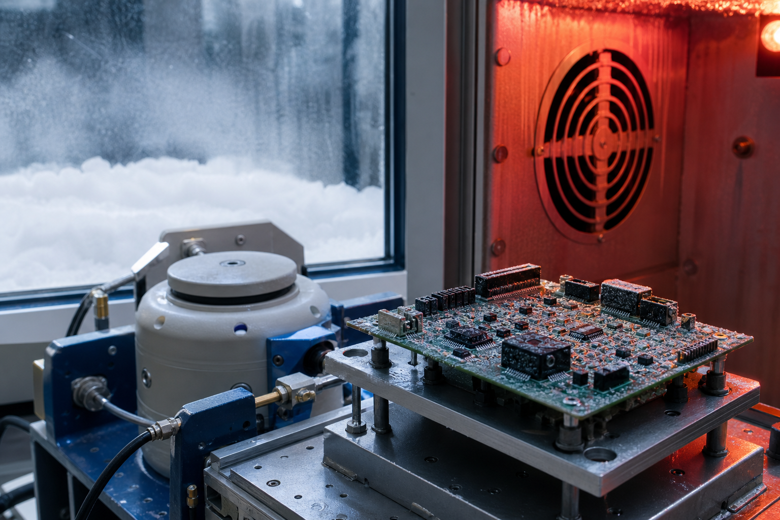 WellPCB delivers advanced automotive PCB service solutions engineered to meet high vibration, thermal, and mechanical demands in modern vehicles. Unlike standard commercial PCBs, automotive PCBs must maintain electrical and mechanical integrity across -40°C to +125°C, resist vibration up to 10G, and withstand continuous thermal cycling. ✔️ IATF 16949, ISO 9001, RoHS/REACH, and IPC-A-610H compliance ✔️ Quick turn PCB prototyping and flexible low to high-volume production ✔️ Full manufacturing and assembly solutions with complete traceability >> GET A FREE QUOTE << | //IMAGE |
//OUR CLIENTS
Serving Leading Automotive Electronics and OEM Markets
WellPCB supports major OEMs, Tier 1 suppliers, and automotive electronics manufacturers with reliable PCB solutions tailored specifically to the automotive industry.
Our PCBs meet rigorous functional safety standards, including IATF 16949:2016, ISO 9001:2015, and IPC-A-610H, facilitating qualification for demanding automotive applications.
Automotive PCBs are used for monitoring and regulating vehicle operation, improving safety, enhancing fuel efficiency, reducing excessive power consumption, and delivering state-of-the-art infotainment systems.
>> REQUEST YOUR FREE QUOTE <<
Comprehensive PCB Manufacturing and Assembly for Automotive Applications
| //IMAGE Engine and Powertrain ControlThese PCBs manage functions such as fuel injection, ignition timing, and transmission control, where precision and reliability are required. To withstand high vibration, temperature extremes, and mechanical stress, we use high-Tg FR4, metal-core laminates, and advanced solder materials. PCB designs follow industry standards, incorporating controlled impedance routing, optimized vias, and copper weights up to 20 oz to support high current loads and mechanical durability. | //IMAGE Battery Management Systems (BMS) and Power Control Units (PCU)Our PCB manufacturing processes apply advanced technologies such as HDI PCBs with microvias, thermal vias, and heavy copper options to manage high current loads and thermal expansion. We optimize PCB design for high reliability, supporting critical functions such as cell monitoring, charge control, and thermal management. To meet automotive industry standards, every PCB assembly undergoes thermal cycling from -40°C to +125°C, temperature humidity testing at 85% to 95% RH, and thermal shock test cycles. |
Advanced Driver Assistance Systems (ADAS) and LiDARWe use high-frequency laminates, such as Rogers and PTFE, to maintain signal integrity at high speeds. Our PCB design incorporates controlled impedance routing, blind and buried vias, and tight trace tolerances to support reliable data transmission. All designs meet automotive industry signal integrity and EMI/EMC performance criteria required for ADAS and LiDAR systems in autonomous driving applications. Each printed circuit board undergoes AOI and X-ray inspection, plus functional testing, to verify accuracy and long-term reliability in real-world automotive environments. | Infotainment and Communication SystemsOur PCB manufacturing uses high-density interconnect (HDI) technologies, flex PCBs, and rigid-flex configurations to support compact, lightweight designs while maintaining durability. We select materials that withstand thermal expansion and contraction cycles and maintain the electrical reliability of circuit boards over long service lives. Each circuit board is verified through AOI, X-ray, and functional testing to meet quality standards and performance-driven requirements for audio, video, wireless communication, and advanced 5G automotive applications. |
Climate Control and Comfort SystemsOur PCB solutions for HVAC, seat heating, and cabin comfort controls use high-Tg FR4, metal-core substrates, and polyimide laminates to withstand extremely hot environments and changing humid environments. Following IPC-A-610H Class 3 standards and other automotive industry requirements, design considerations include expansion and contraction management, optimized thermal vias, and solder joint reinforcement to maintain durability. |
Types of Automotive PCBs We Can Manufacture
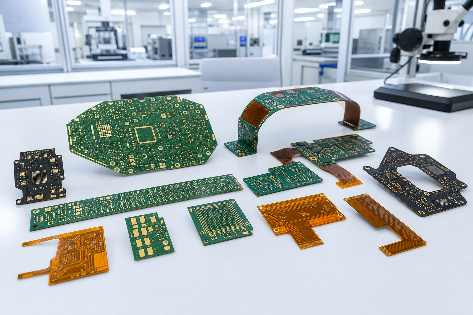
| //IMAGE Metal Core PCBsOur metal core PCBs provide enhanced thermal management and mechanical strength for power control units, LED lighting, and motor control systems. We offer aluminum and copper core options to support heat dissipation and maintain stability under thermal shock and vibration conditions.
| //IMAGE Flexible/ Rigid-Flex PCBsOur flexible/rigid-flex PCBs enable compact, lightweight designs used in dashboards, sensors, and space-constrained areas of modern automobiles. We apply polyimide laminates for high flexibility, heat resistance, and the ability to withstand expansion and contraction without mechanical failure.
|
| //IMAGE Heavy Copper PCBsWe manufacture heavy copper PCBs for applications requiring high current capacity and thermal dissipation, including powertrain controls and electric vehicle power distribution units.
| //IMAGE Ceramic PCBsOur ceramic PCBs offer excellent thermal conductivity and dimensional stability for high-temperature, high-reliability automotive electronics. These are often used in engine sensors, power electronics, and LED drivers where heat management and mechanical durability are required.
|
| //IMAGE HDI PCBsWe deliver HDI PCBs that support advanced driver assistance systems, infotainment, and complex control modules. These boards include microvias, blind and buried vias, and fine-line trace structures that enable compact, high-functionality designs with reduced signal loss.
| //IMAGE High-Frequency PCBsWe manufacture high-frequency PCBs using materials like Rogers and PTFE laminates for radar, ADAS, and LiDAR systems. Designs emphasize controlled impedance, minimal signal loss, and durability to maintain performance under thermal cycling and vibration.
|
Our Automotive PCB Service Capabilities
MaterialsWe offer a full range of automotive-grade materials selected for mechanical strength, heat resistance, and electrical performance. These include FR4, metal core, Arlon, Taconic, Nelco, Isola, Halogen Free, Rogers, PTFE, PI, etc.. All material selections follow ISO9001, IATF 16949, IPC-A-610H, and IPC6012E specifications for thermal cycling resistance, dielectric performance, and vibration durability. Choices are based on thermal expansion needs, vibration resistance, and application-specific requirements to ensure high reliability in demanding environments. |
Various PCB Board TypesWellPCB manufactures single-layer, double-layer, multilayer up to 50 layers, rigid-flex, flex PCBs, and HDI PCBs. This range supports simple control boards to complex, space-constrained designs used in modern automobiles. All stack-ups and constructions follow standard design guidelines to achieve controlled impedance, thermal management, and compliance with IATF 16949, IPC-6012E, IPC J-STD-003B, and IPC-TM-650 performance standards. |
Trace Width and SpaceOur manufacturing process supports fine-line fabrication. The minimum trace width /space for the inner layer is 2.5mil/2.5mil, while the minimum trace width /space for the outer layer is 2mil/2mil. This precision enables compact designs with controlled impedance routing, optimized signal integrity, and efficient use of board area. All designs are modeled to meet signal integrity requirements and EMI/EMC compliance for high-speed automotive systems. |
Copper ThicknessWe provide copper thickness options up to 20 oz for heavy copper PCBs. This supports high-current automotive applications where thermal management and mechanical durability are required, such as power control units and electric vehicle battery systems. Copper thickness designs are validated to AEC-Q200 current-carrying capacity standards and IPC-6012E acceptance criteria. |
Via StructuresOur PCB designs include microvias, blind/buried vias,via-in-via, via-in-pad, and stacked vias. These structures support high-density interconnects, heat dissipation, and reliable performance in automotive printed circuit boards exposed to thermal cycling and mechanical stress.
|
Choice of Surface FinishesWe offer a variety of surface finishes, including HASL, lead-free HASL, OSP, immersion silver/ tin, ENIG(+ G/F), ENEPIG, and bare copper. These finishes provide excellent solderability, corrosion resistance, and compatibility with leaded and lead-free assembly processes. |
Advanced ProcessesOur advanced processes and technologies include:
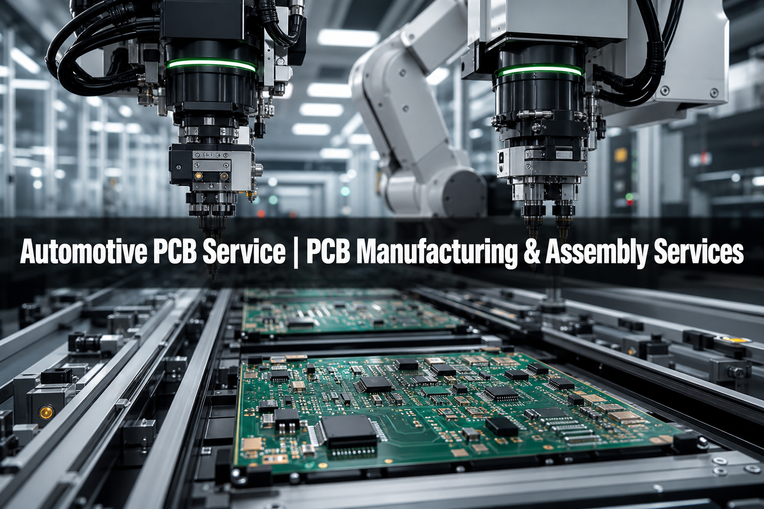
All assembly and inspection procedures follow IPC-A-610H Class 2 & 3 workmanship standards and IATF 16949 automotive standard. We also operate BGA rework stations for precise ball grid array assembly and repair. |
Prototype ServicesWellPCB offers quick-turn PCB prototype manufacturing with delivery options as fast as 72 hours for 12-layer PCBs, 120 hours for 12+ layers PCBs. Prototypes are built to the same standards as production units, ensuring accurate validation. |
Production VolumeWe provide flexible production volumes from low to high-volume runs. Minimum quantities vary based on layer count and automotive qualification requirements, as complex boards may require batch minimums for AEC compliance testing. Customers can align orders with development, pilot production, or full-scale manufacturing needs without excess cost. |
Quality ManagementOur quality management system is certified to IPC-A-610H Class 2 & 3, ISO 9001, and IATF 16949 standards. We also align with IPC-6012E, IPC J-STD-003B and IPC-TM-650 qualification protocols, applying thermal cycling, humidity, and mechanical stress testing as required. |
>> CONTACT US <<
Why Choose WellPCB As Your Automotive PCB Service Provider?
| //ICON Support for PCB Design and ManufacturabilityOur team collaborates with you to review PCB layouts, material selections, and stack-up configurations. We provide engineering support to optimize manufacturability and long-term reliability. Design recommendations align with automotive industry standards to minimize production risks and ensure qualification readiness. | //ICON Reliable PCB Manufacturing and Assembly with Full TraceabilityWellPCB’s manufacturing and assembly processes follow strict quality management system standards. We maintain IPC-A-610H, IPC-6012E, ISO 9001, and IATF 16949 certifications. Traceability records support IPC-A-610H, IAFT 16949, and ISO 9001 audits, providing inspection reports, process controls, and documentation for compliance and reliability verification. | //ICON Rapid Prototyping and On-Time DeliveryWe offer quick-turn PCB prototype production with delivery options as fast as 72 to 120 hours. Prototype builds meet the same standards as production runs, allowing early validation. For larger volumes, our production planning system ensures on-time delivery according to your requirements for pilot runs or full production batches. |
| //ICON Secure File Upload and Fast Online QuotesYou can upload your files securely through our website for fast online quoting. We accept Gerber files, BOMs, and tolerance documents to provide fast, accurate quotes and begin the production process without delays. | //ICON Application-Specific Material and Process SelectionWe match materials and fabrication processes to the unique requirements of each automotive application. This includes selecting suitable laminates, copper weights, and via structures for power electronics, ADAS, lighting, and communication systems. Material and process selections follow IPC-A-610H, IAFT 16949, and ISO 9001 criteria to support both high-frequency and high-current demands. | //ICON Built-in Resistance to Vibration, Heat, and HumidityEvery PCB is engineered to withstand mechanical stress, high vibration, and temperature fluctuations. Material choices such as high-Tg FR4, metal-core laminates, and polyimide ensure thermal stability and durability. All designs undergo testing per IPC-A-610H and IATF 16949 standards, including thermal cycling from -40°C to +125°C, humidity testing at up to 95% RH, and vibration durability testing. |
Our Automotive PCB Testing Process
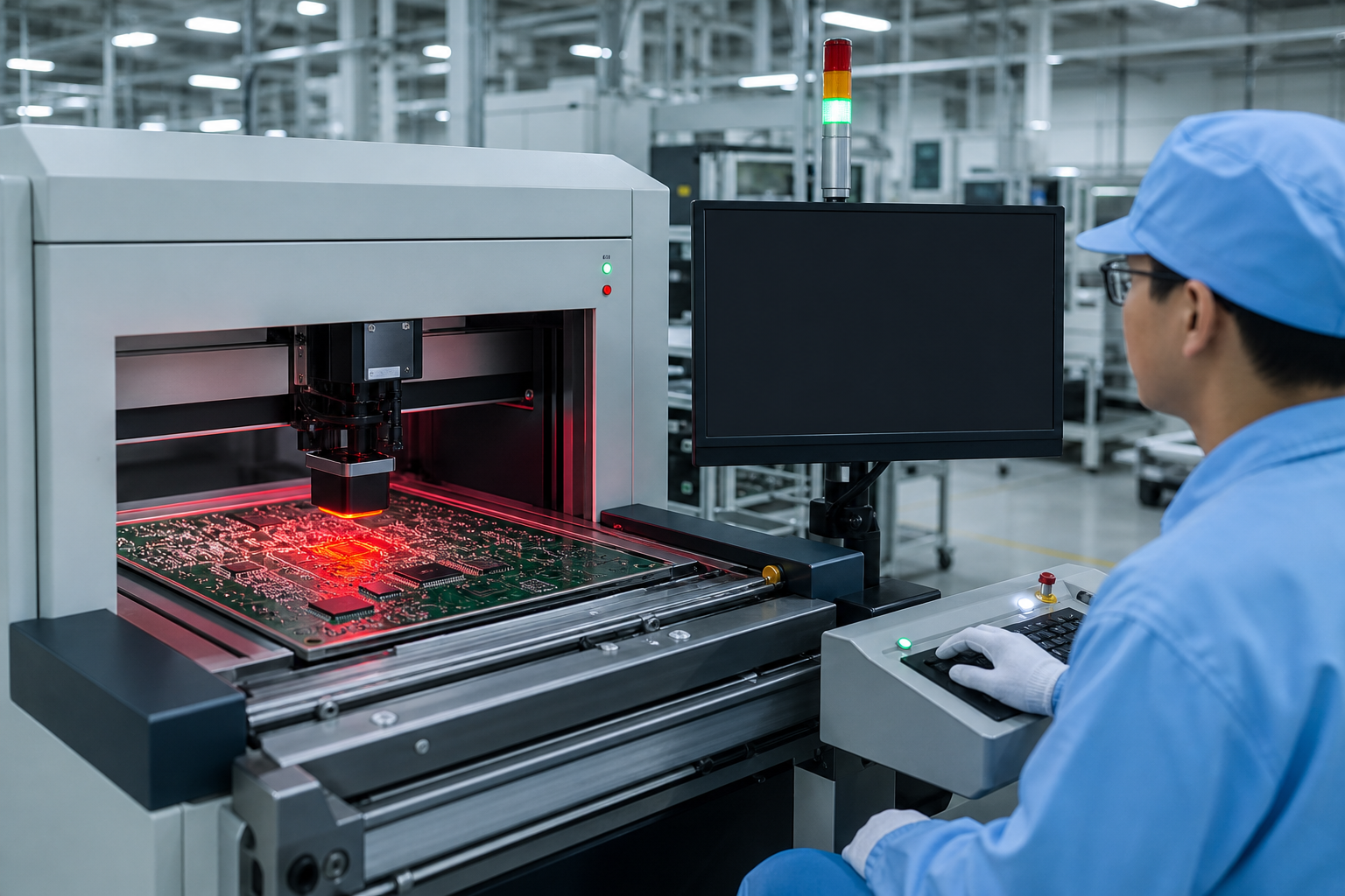
WellPCB applies a rigorous testing and quality management system to detect defects, verify mechanical integrity, and confirm electrical functionality under the demanding conditions used in automotive applications. This includes:
| //ICON Cross-Section and X-ray AnalysisCross-section analysis involves cutting a sample PCB and polishing the cut area to examine internal layer alignment, via walls, plating quality, and solder joints under a microscope. This allows us to measure plating thickness, detect voids, and evaluate copper distribution. Analyses are performed according to IPC-TM-650 acceptance criteria. X-ray inspection uses high-resolution imaging to visualize hidden solder joints, internal vias, and component placements. This method identifies cold solder joints, insufficient plating, and internal fractures without damaging the board, following IPC-A-610 Class 2 & 3 workmanship standards. | //ICON Thermal Cycling and Thermal Shock TestingThermal cycling subjects PCBs to repeated temperature changes between -40°C and +125°C, simulating long-term operational stresses. Boards are exposed to at least 1000 cycles in environmental chambers following AEC-Q100 qualification protocols. Thermal shock testing moves PCBs rapidly between two chambers at extreme temperatures to assess the effects of sudden expansion and contraction. Thermal shock durations and ramp rates meet AEC-Q200 environmental testing requirements to confirm that materials, vias, and solder joints maintain mechanical and electrical integrity. |
| //ICON Temperature Humidity TestingTemperature humidity testing places PCBs in a controlled chamber with 85% to 95% relative humidity and elevated temperatures from 85°C to 95°C, simulating exposure to changing humid environments. Testing cycles follow AEC-Q200 stress testing protocols. Electrical performance is monitored continuously, and boards are inspected for delamination, corrosion, and material degradation during and after testing. | //ICON Vibration and Mechanical Stress TestingVibration testing mounts PCBs onto fixtures connected to multi-axis shakers, simulating real-world automotive vibration profiles. Testing follows IPC-6012DA criteria and SAE J1211 vibration standards. Mechanical stress testing includes tensile and compressive force application to validate the strength of vias, solder joints, and component placements. Testing validates conformance to AEC-Q200 mechanical durability benchmarks for high-vibration and shock environments. |
| //ICON Electrical Testing and AOIElectrical testing applies voltage and current using programmable digital power supplies, oscilloscopes, signal generators, multimeters, and high voltage testers. Tests verify continuity, detect shorts, and validate circuit functionality under operating conditions. All electrical testing aligns with IPC-9252 testing standards and AEC-Q100 functional testing protocols. Automated Optical Inspection (AOI) uses high-resolution cameras and pattern recognition, while AI inspection assists with defect detection and process control. | //ICON Traceability and Quality DocumentationWe assign each production lot a traceable identifier linked to tolerance documents, inspection reports, and process data. Traceability records support AEC-Q100/200 audit readiness, ISO 26262 functional safety assessments, and compliance verification for IPC and IATF quality management systems. This supports root cause analysis and customer audits. |
>> GET A FREE QUOTE <<
Automotive PCB Service: Client Feedback
//REVIEWS CAROUSEL
Automotive PCB Service | FAQs
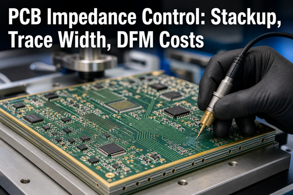
How do you handle controlled impedance requirements in automotive PCBs?Our engineering team reviews impedance control requirements during the design phase. We calculate trace width, spacing, and dielectric thickness based on material properties and signal speed. Automated impedance modeling software is used, and impedance is verified during production with time domain reflectometry (TDR) testing. All impedance control designs meet IPC-A-610H and IATF 16949 signal integrity criteria for high-speed and RF automotive applications. |
Can you accommodate design for high-current automotive PCBs?Yes. For high-current applications such as power distribution units and motor controllers, we offer heavy copper PCBs with up to 20 oz copper weight. We design trace widths and thermal vias to handle expected current loads and manage heat dissipation. All designs are validated to IPC-2152 current-carrying capacity standards and AEC-Q200 thermal management requirements. |
How do you manage dimensional tolerances for rigid-flex and flex PCBs?We apply CNC machining with tight dimensional controls and use laser cutting for flex circuit outlines. We follow IPC-2223 and IPC-6013 standards for dimensional tolerances. Production monitoring includes optical measurement and cross-section inspection, ensuring compliance with AEC-Q200 mechanical tolerance requirements and confirming layer alignment to design specifications. |
What are your average lead times for automotive PCBs?Standard lead times range from 4 to 25+ days, depending on the size, layer count, and volume of your PCB order. |
WellPCB: Your One-Stop Automotive PCB Service SolutionWellPCB delivers cost-effective, high-reliability automotive PCB manufacturing and assembly services backed by world-class engineering support and comprehensive solutions for the automotive industry. >> GET YOUR FREE QUOTE << |